
Hi, my name is Thomas
and this is the engine that I'm converting for use in a Spacek SD-1 Minisport (single-seat, 255kg MTOM, 90-95kts cruise)
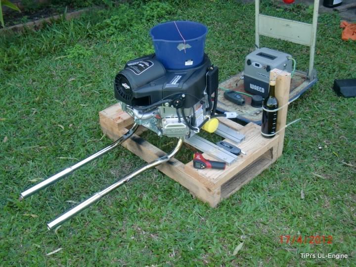
The Donor Engine
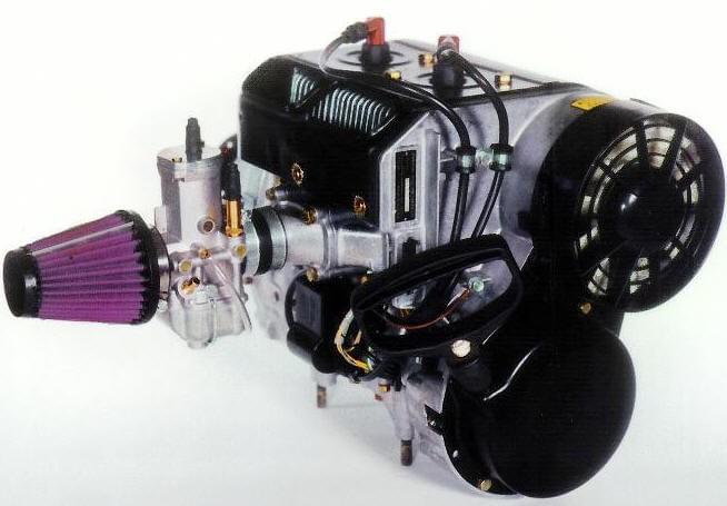
The engine is a mass-produced industrial V-twin, with a displacement of 810cm3 (49CI). Due to legal implications, I can't name the manufacturer but it is visible on the stickers. The original is a vertical shaft engine so it will require some modifications to turn it horizontal.
Why did I choose this engine?
- it is the lightest, mass-produced engine in this displacement/hp size
- has forged crankshaft and conrods
- is built for professional applications (zero-turn contract mowers)
Expected Outcomes
The engine in it's OEM configuration is rated from 26 to 30hp (at 3,300 to 3,600rpm, depending on model) and weighs 40kg. My aim is to have a completed engine with propeller, exhaust, engine mount and oil tank for under 40kg. The engine output is expected to be around 35hp at the same 3,600rpm.
The video on the right has the interesting bits from around 1:30

Why Upside-Down?
I have decided to install this engine in an "Upside-Down" style eg the cylinder heads hanging, crankshaft above:
- keep the propeller axis high (ground clearance), allows larger prop diameter
- the cowling will be smooth on top, no cylinders or bumps sticking out
- the engine in this configuration will fit inside the firewall outline
- The oil pump is on the low side of the engine (below the crankshaft)
- Using a dry sump system will simplify the oil system conversion (oil draining from the 2 rocker covers)
- cooling air entry from below the propeller into a "plenum" formed by the cylinders
- exhaust pipes are already towards the bottom of the engine and will have a very short length inside the cowling (not adding much heat)
Steps to Modify This Engine
In brief, these are the planned steps so far:
- establish operating conditions in original configuration (temperatures, pressure, power etc)
- convert the oil system from wet sump to dry sump (to facilitate the horizontal orientation)
- modify the oil pump suction port for the external oil supply
- port the intake ports, valve seats, valves and exhaust ports
- install an aluminium flywheel (carrier for ring gear, alternator and ignition magnets). The propeller will be the main rotating inertia.
- strip all unnecessary weight
- remove the governor
- make a new intake manifold, tune the carburetor and add a cockpit-adjustable mixture control
The new 4-stroke replacement for smaller 2-stroke engines
This 35hp V-twin is suitable to replace 2-stroke UL aircraft engines in the 30 to 40hp range (as direct-drive for faster aircraft). Similar weight, 2/3 of the fuel burn (less weight), no oil mixing, reliable 4-stroke operation and a nice sound.
V-Twin 35hp
- Type: 4-stroke V-Twin
- Bore: 83.8 mm, Stroke: 73.4 mm
- Displacement: 810 cc
- Compression ratio: 8.4 (stock), ~9 (modified)
- Reduction gear: optional
- Power output: 35 hp (26 kW) at 3,600 rpm
- Fuel consumption: 8-9 lph full power, 5-7 lph at 75% (to be confirmed)
- Dry weight: 32-34 kg (engine with electric start & alternator)

Rotax 377
- Type: two-stroke, 2-cylinder in-line, air-cooled aeroengine
- Bore: 62 mm, Stroke: 61 mm
- Displacement: 368 cm3
- Power output: 26 kW (35 hp) at 6500 rpm
- Fuel consumption: 450g/kWh (16 lph at full power, 10-12 lph at 75%)
- Dry weight: 38.4 kg (complete including reduction drive and exhaust system)
Rotax 447
- Type: two-stroke, 2-cylinder in-line, air-cooled aeroengine
- Bore: 67.5 mm, Stroke: 61 mm
- Displacement: 426 cm3
- Compression ratio: 9.6 theroretical, 6.3 effective
- Power output: 30kW (40hp) at 6,800rpm
- Fuel consumption: 450g/kWh (18.5lph at full power, 11-13lph at 75%)
- Dry weight: 42 - 45 kg with electric start

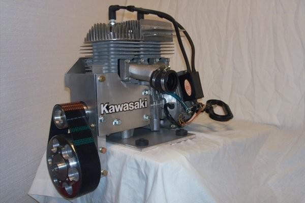
Kawasaki 440
- Type: two-stroke, 2-cylinder in-line, air-cooled aeroengine
- Bore: 68 mm, Stroke: 60 mm
- Displacement: 436 cm3
- Power output: 38 hp (28 kW) at 5,000 rpm
- Dry weight: 49 lb (22 kg), no re-drive, exhaust or electrical system
- Reduction gear: aftermarket reduction drive for aircraft use
Progress of the testing and conversion
Unfortunatley, progress is rather slow, work keeps getting in the way!

Oil tank: the external oil tank with a built-in air-oil separation screen (1.5lt of oil, 0.7lt of space)

Mapping of the intake and exhaust lobes (timing, lift & duration, lobe separation etc). The camshaft might need some light grinding to get a bit more power.

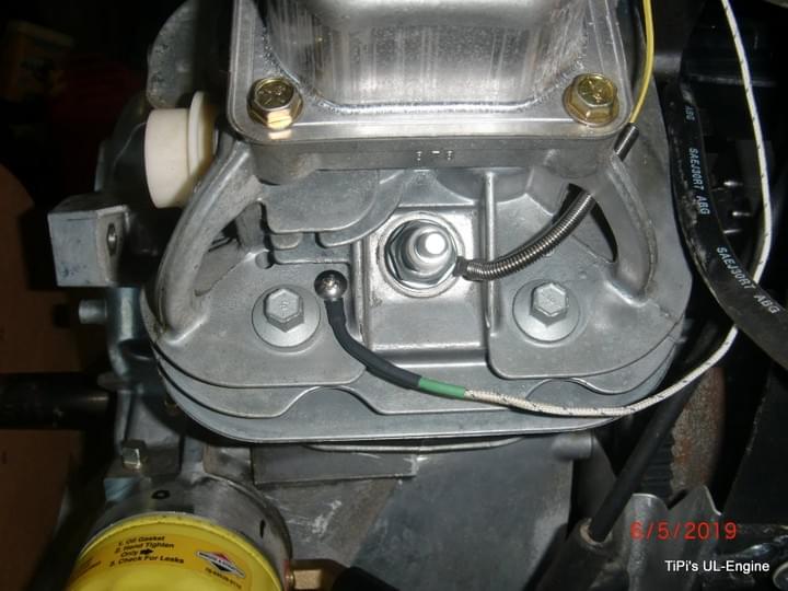
CHT probes installed (one under each spark plug and a separate permanent probe)

Test club to measure engine output (one built, several other sizes planned)

Oil pressure and oil temperature sensor holes drilled, tapped and sensors installed. The oil temp is after the oil cooler (RH fitting to the oil cooler). Another sensor is located in the oil tank (hottest part of the oil circuit).

I found a Rotax bulletin on how to establish the inertia of propellers. I used the same concept and a series of calculations to work out what the rotational inertia is for the flywheel compared to the propeller. It works out that the flywheel has approx 500kg*cm2 at 6.7kg weight vs the prop with 1,150kg*cm2 at 2.04kg weight (1.25m dia). This means that the prop has over twice the rotational inertia at 1/3 the weight = flywheel not needed (only to carry the starter ring gear, alternator and ignition magnets).

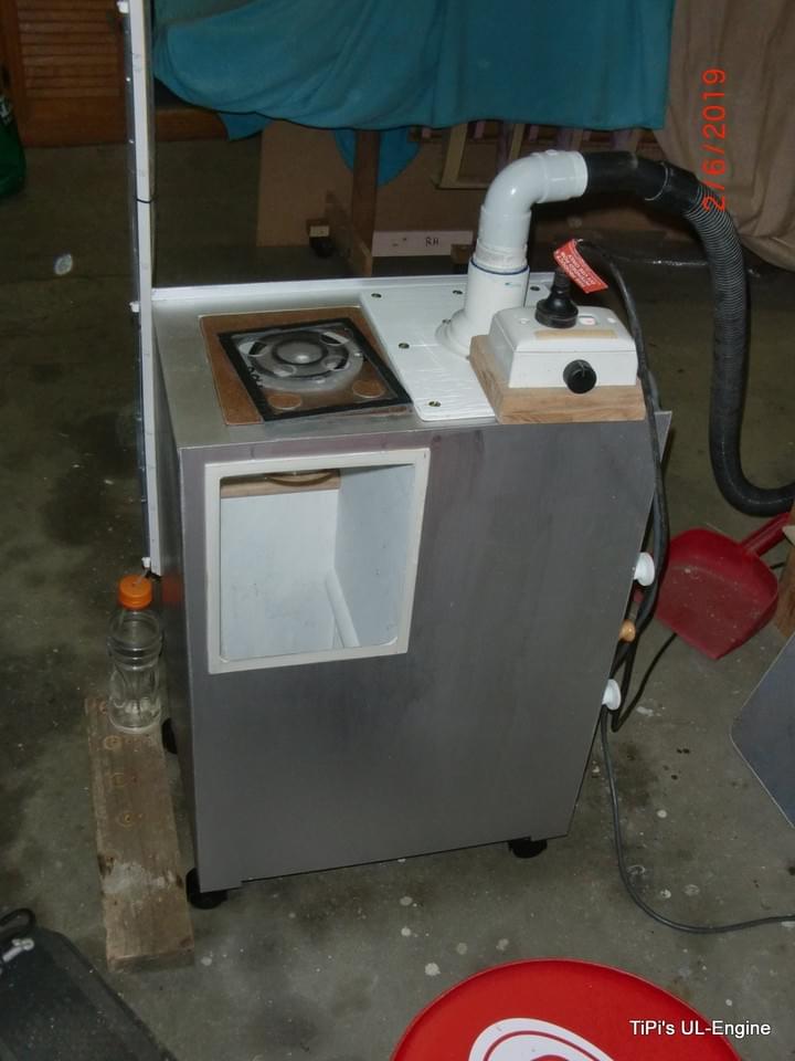
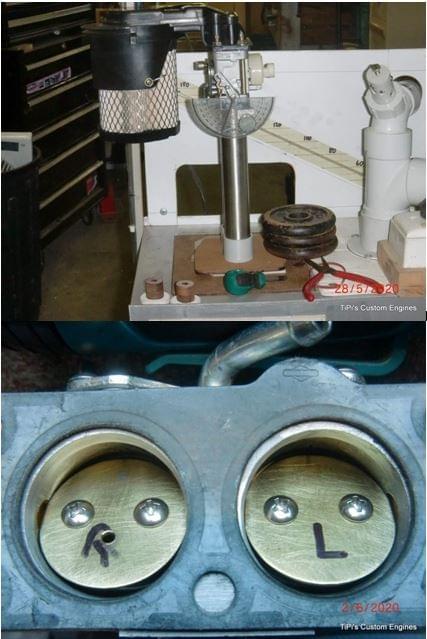
This is a home-built flow bench. I designed it to suit the size of the cylinder heads and flow rates of the V-Twin. It will be used to evaluate and quantify modifications to the carburetor, intake manifold, cylinder head ports, valves & valve seats and exhaust. The orifice plates are not calibrated, so the data is a relative measure rather than an absolute (cfm flow rates)

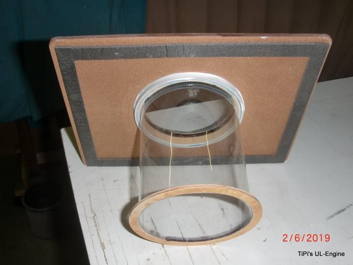
The see-through cylinder of the flow bench. It simulates the actual cylinder in the engine to more accurately represent the flow of the air through the valve (restrictions by the cylinder wall).
The flow bench design is based on a publicly available design (plus more) from DTec (http://www.dtec.net.au/Tech%20Articles.htm), modified to suit this particular application.

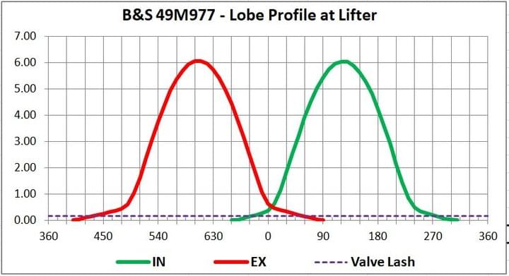
This is the camshaft lobe profile recorded. The EX lobe has an excessive ramp on both sides, information I have found indicates that this is as a "built-in" EGR circuit. Also, the lobe separation is a bit on the large side for a low revving engine (119°).

The valve seat cutting kit has arrived, AUD500 for what you see!
But it will allow me to cut the seats correctly and maximise airflow through the ports.
So far I have the 45° seat cutter and the 15° and 75° top and bottom narrowing cutters.
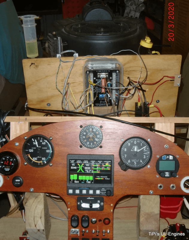
Some progress! The engine is all wired up to the MGL Xtreme EFIS (with the RDAC module). Most sensors are working but I still need to sort out a few problems before starting on the first performance tests.

The engine is mounted in the safety cage and has been run at full power. Unfortunately, the result is rather disappointing, the engine only produced around 23-24hp as tested with the 760mm club. Some more work is required to get the engine to deliver the factory rated output (30hp gross for this engine, I would be happy with 27-28 with fan and air filter/intake system).
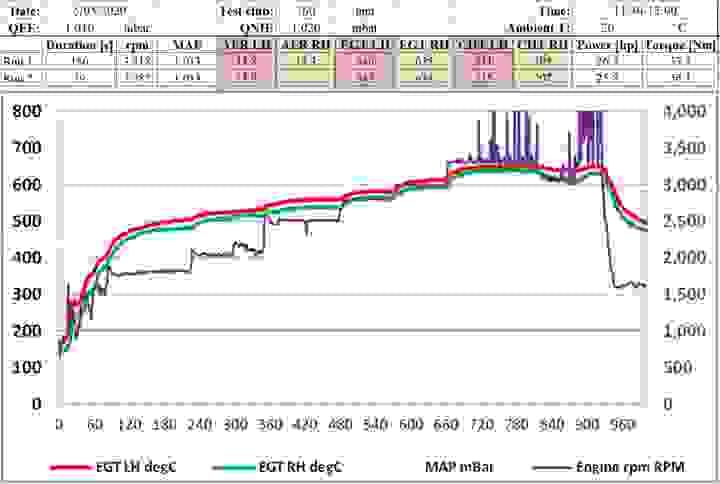
The results are in: the engine is capable of producing about 27-28hp with a little bit of tweaking (mixture, ignition timing, cleaning up of intake manifold joins, cleaning of carburetor throat). Removing the fan would get another 1-1.5hp, so pretty close to claimed output (30hp). The biggest challenge was getting an accurate rpm reading. The ignition signal seems to be a bit variable and the MGL instrument fluctuated widely. I had the most success with an externally mounted Hall sensor (Arduino) and a signal inverter transitor (until it started to play up).
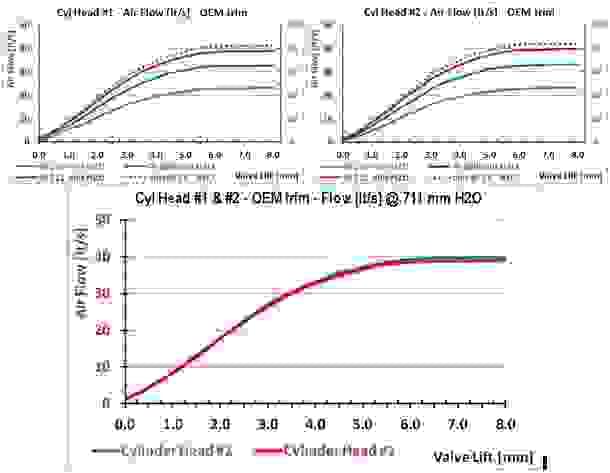
The first cylinder head flow tests (intake port) have been completed. The results show a clearly visible choking point at 5.5mm of valve lift. This is the point where the valve opening (valve curtain) is no longer the limiting part of the intake tract. Increasing the valve lift doesn't increase the flow any longer. The flow is now choked due to the port design, size and valve shrouding.
Time to get the die grinder out.
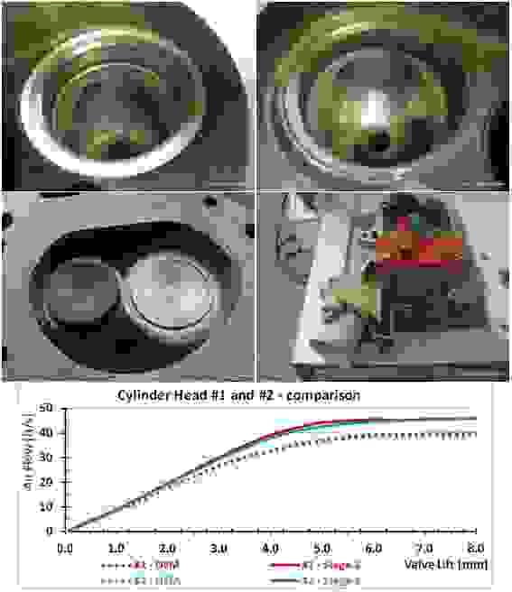
Intake port: 3-angle valve seat cut, port smooting and blending, unshrouding the valve
Result: flow improvement of around 13-15%
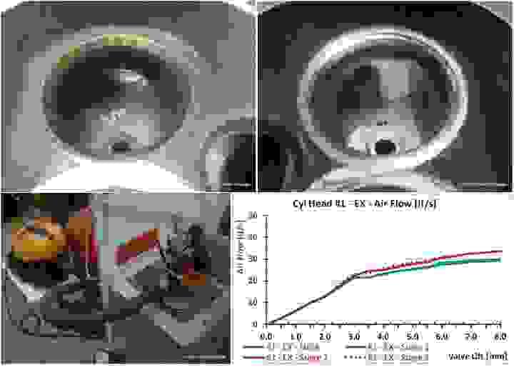
Exhaust port: 3-angle valve seat cut, port smooting and blending, unshrouding the valve
Result: flow improvement of around 10% (all improvements are at valve lifts >3mm)
Both ports have a right angle intersection and a very sharp short turn (inside) radius, not helping to maintain a good flow.
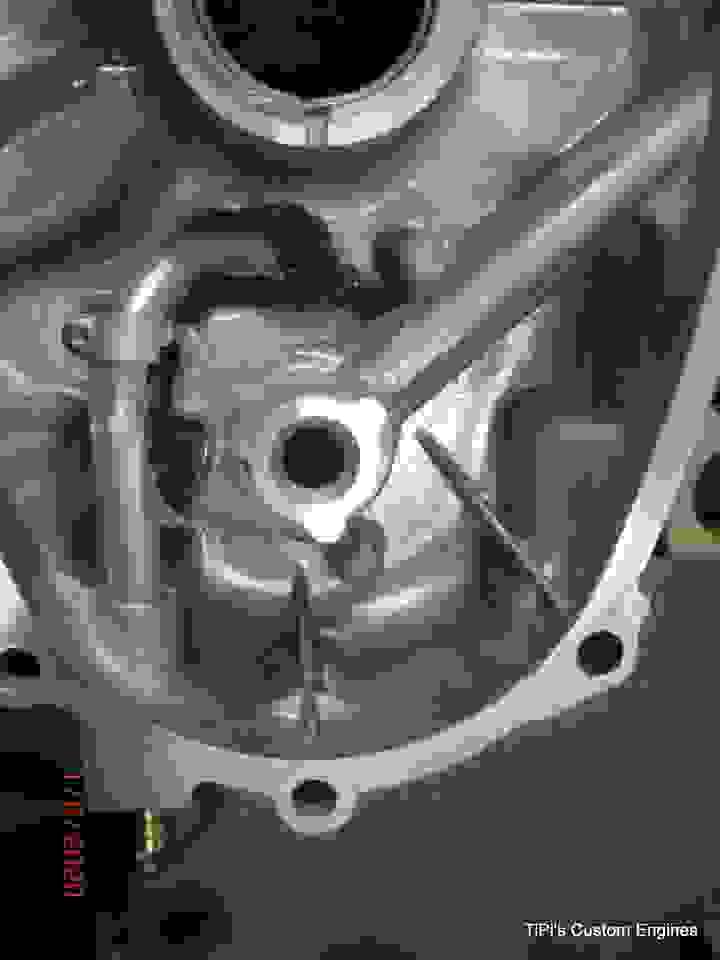
Oil pick-up for the dry-sump system: the hose from the external tank will connect to the hose barb fitting at the bottom, then the aluminium tube connects it to the original oil pump inlet (matched and sealed off to the cover)

When flow-testing the carburetor, the RH barrel was flowing nearly 15% less at idle settings. A 2.5mm hole drilled in the throttle plate evened the flow between the 2 barrels (important for a steady idle speed). There are no adjustements for idle air or idle fuel possible (only by drilling out jets/passages).
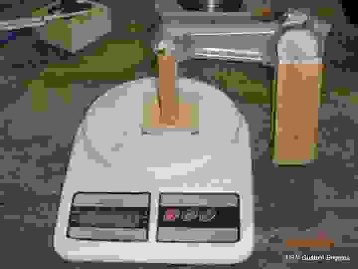
Time for some blue-printing: weighing the rotating and reciprocating parts. The weight differences are surprisingly small (generaly less than 1g).

Mock-up of the exhaust manifold and carburetor location. the intake port is counter-bored, the flanges are drilled at the angles for the mainfold to have a straight connection. Same for the exhaust manifold to have a clean line-up of the port and pipe.

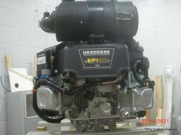
My new engine, a 28hp Vanguard EFI. I have yet to hook it up and test the power output with the test club.
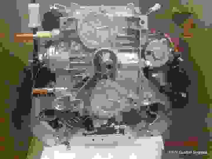
It is the version with a built-in scavenge pump for the OilGuard system (external sump engine)

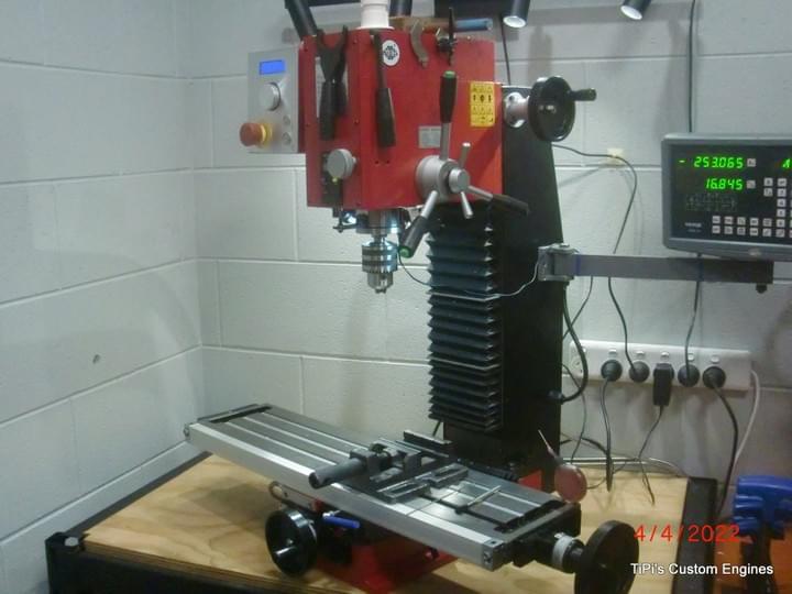
My small mill with 2-axis DRO (Sieg SX2.7L)
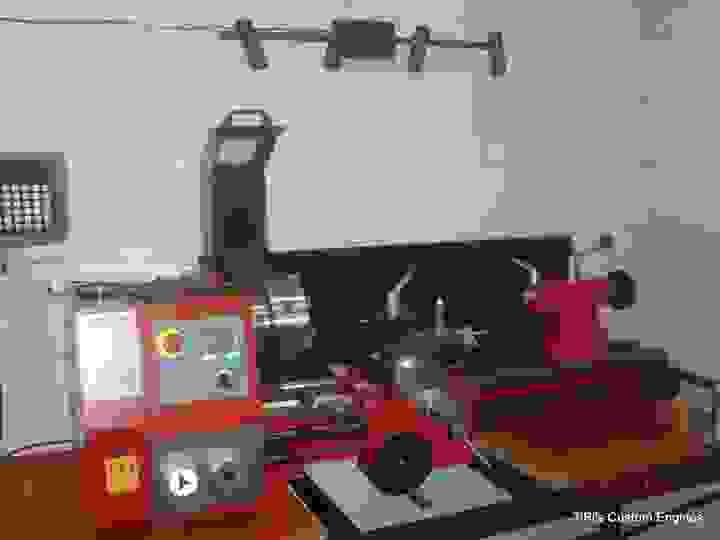
My Sieg SC10 lathe

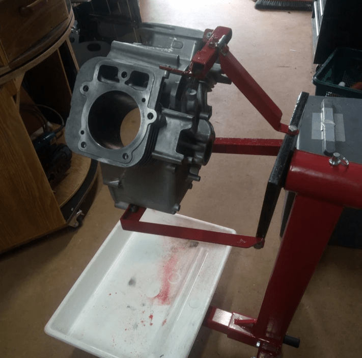
Adaptor for my engine assembly stand, started the final assembly
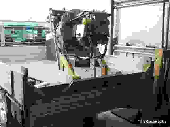
The engine is assembled, test stand built and has run for a few minutes. The oil return system (dry sump) works as designed, more work is needed on the carburetor/intake system (poor running).
About me
Hi, my name is Thomas and I'm building the SD-1 Minisport at my home in Peeramon on the Atherton Tableland, Qld (Australia). I'm also converting my own engine as described above.
I have the intention of making parts or complete engines available to people who are looking for a 4-stroke replacement of Kawasaki 440 (28hp), Rotax 377 (35hp) or even 447 (40hp) 2-stroke engines. As direct-drive, this engine would only be suitable for faster Ultralights (70kts plus), slower aircraft would need a re-drive to get sufficient thrust (or run larger props at lower rpm).
I'm a qualified motor mechanic, have a BSc in Automotive Engineering and have worked for many years as Reliability Engineer on large mining equipment. I'm also a qualified RA-Aus L2 (recreational aircraft maintenance).
Please contact me if you are interested in this engine concept.
If you are interested in much more detail of this conversion work, please check out the blog on HBA (www.homebuiltairplanes.com) or click on one of the buttons top right (HBA Blog or HBA Blog Q&A)
- Contact Us
© 2019


